Ready, Set and Install!
Back to: Installing a Parrot Interactive LED on a surface
Prepping before Installing:
always ensure that you have the correct PPE equipment that is required by your company for installing. Items such as gloves, dust masks or goggles would be helpful while drilling and make sure that you have a capable assistant with you to lift the LED into place. Also make sure that you have all tools and sundries at hand.
Prepare your surface, remove any protruding or obstructions and begin. You can refer to any measurements in the user manual of the LED’s if you are not sure on the first couple of installations. There are guidelines to install listed in section 2.3 in the user manual.
Parrot Interactive LED User Manual
Measurements:
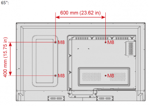
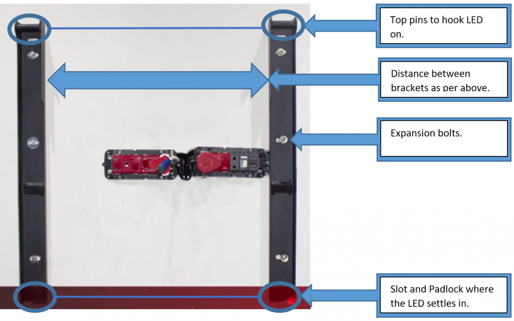
The bracket distances will differ between the three variants of LED’s available. The measurement below illustrate the distance between the bracket mountings on the back of the LED.
65″ LED bracket measurement
75″ and 86″ LED Bracket Measurement
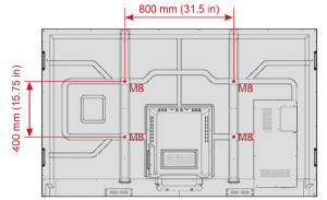
The above images illustrates the exact measurements for the brackets to be mounted to the surface. You will find the center point of where the LED needs to go and measure for example using the 65″ 300mm to each side of the central point (total width then being 600mm) and then mark your bracket holes.
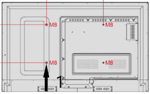
Also it is recommended to measure the distance from the bottom of the bracket to the bottom of the screen to use as the baseline / height of the screen installation Marked as 1 in the below image:
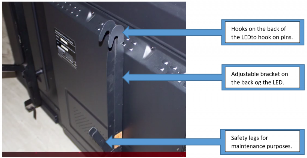
**You would need to mount the back brackets to the LED
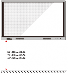
The recommended heights for LED installations listed below can be adjusted to customer satisfaction. This means that you would need to access the customers needs and decide on the heights from there. We at parrot normally install that the bottom of the LED is between 900mm and 1M from the ground but you can decide.
Mounting the brackets (AL5000)
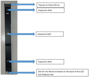
Keeping in mind the point above to measure from the bottom of the bracket to the bottom of the screen will assist us in getting the correct height to our LED. The brackets need to be mounted with three Roll bolts per side to ensure maximum strength for maintenance and functional purposes.
- Measure the LED distance from the bottom of the bracket to the bottom of the LED
- Take your measuring tape and measure the complete distance to the first hole
- Place the bottom of the bracket on the marked line. Apply this at the required distance for both brackets
- Mark the three point where you will be drilling your holes.(On both brackets)
- Take a spirit level and ensure that what you have marked is level
- Take your 14mm drill bit and ensure the drill is set to hammer action. Drill the first three holes and place the Roll bolts in the holes
- Slightly tighten the bolts so that it may expand in the whole and then only remove the bolt
- Place the bracket and slightly tighten the bolts. Do this on both side
- Take your spirit level and ensure that the two brackets are the same height and level
- Once level, you may tighten the expansion bolts.
- Ensure that they are securely tightened to eliminate any possibility of the expansion bolts pulling out of the surface
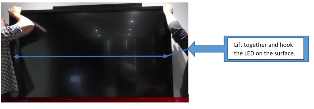
- Now that you are satisfied with the brackets you may lift the LED (with the already mounted brackets) and hook it onto the surface.
**Make sure that the brackets are correctly mounted one the wall and behind the LED as there are slots that it slides into allowing you to lock it in place with a padlock. If this is not done correctly the LED will stand slanted upwards
Lifting and installing the LED:
The below illustrates how an LED can be lifted and mounted onto the surface after completion of the brackets.
Installing the OPS PC:
Here are the steps to install the OPS pc if it is part of the solution:
Step 1 Unscrew the M3 screws by hand to remove the internal PC shielding cover.
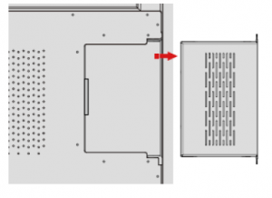
Step 2 Push the internal PC into the port at the rear of the screen from right to left.
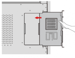
Step 3 Secure the internal PC to the display by using the M3 screws.
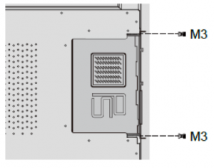
Step 4 Ensure the installation is correct before turning the power on again.
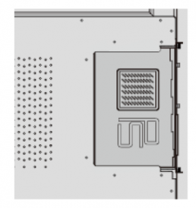
Once hooked on you can install additional add ons as described in the Product knowledge section:
- Sound bars can be mounted on top or below the LED with 2 X 6mm Screws and fisher plugs
- Wireless presentation device can be mounted on the side of the LED with 2 X 6mm screws and fisher plugs
- VC (Video conferencing) system – Camera mounted on top of the LED to the surface and the Speaker pod either on the table or mounted against the wall on the side (Bracket would need to be custom made).
- An additional projector trolley could be purchased for placing
- Visualizers
- Graphics Tablets
- Wireless casting device dongles
- etc.
