Ready, Set and Install!
Back to: Installing / mounting a Parrot Interactive LED on a Stand
Prepping before Installing:
Always ensure that you have the correct PPE equipment that is required by your company for installing. Items such as gloves, dust masks or goggles and make sure that you have a capable assistant with you to lift the LED into place. Also make sure that you have all tools and sundries at hand.
Prepare your area, remove any protruding or obstructions and begin. You can refer to any measurements in the user manual of the LED’s if you are not sure on the first couple of installations. There are guidelines to install listed in section 2.3 in the user manual.
Parrot Interactive LED User Manual
Measurements:
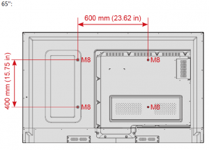
The bracket distances will differ between the three variants of LED’s available. The measurement below illustrate the distance between the bracket mountings on the back of the LED.
65″ LED bracket measurement
75″ and 86″ LED Bracket Measurement
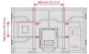
The above images illustrates the exact measurements for the brackets to be mounted to the surface. Because this is a mobile solution you can mount the brackets to the back of the LED and there will be ample space to hook it on the stand.
By adjusting which hole your screws are in on the back of the LED it will determine how high or low the LED will stand in front of your client.
Building and mounting the screen:
When it comes to assembling the IW7101 stand it is very simple. The stand also comes with a manual on how to install but for your reference it can be acquire from the link here:
IW7101 – Interactive Touch Panel Stand Part 1
IW7101 – Interactive Touch Panel Stand Part 2
This is what you can expect the box and content to look like:
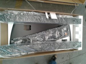
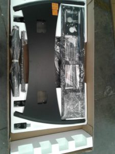
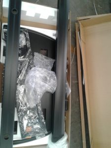
We will go through some of the steps in the manual to ensure that you are fully aware of what is needed.
Figure A
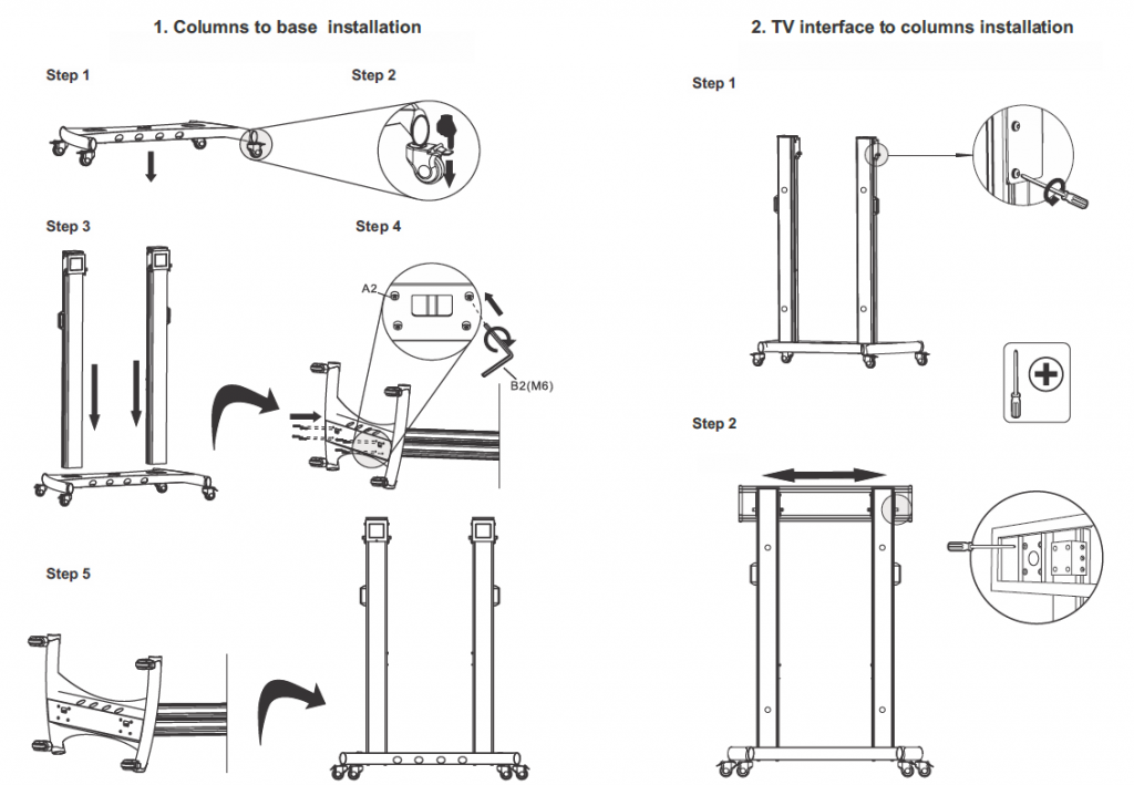
Points to remember when doin the above:
- If you are using the accessory tray(Figure C step 5) you need to insert it first before Figure A Step 2.
- Everything is hand tightened so when you do use a cordless drill or screwdriver, please ensure to not strip the bolts.
Figure B
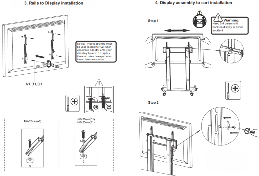
Figure C
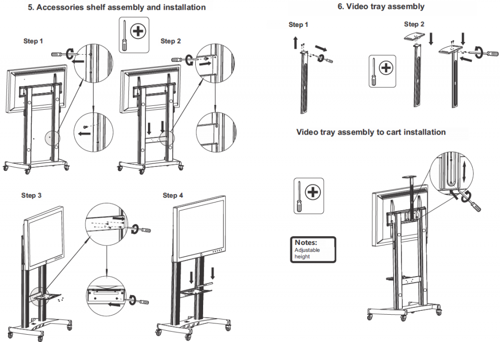
Figure D
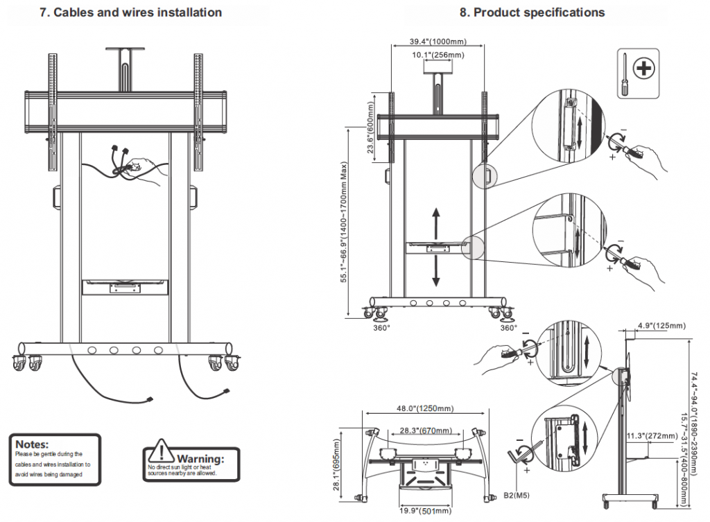
Points On cable management:
- As you can see from Figure D Step 7, there is a cable management system available to you. Use this to ensure a neat and safe environment. If used accordingly there is no possibility of cables hooking or getting stuck
- Be careful with you cables, for example: An HDMI cable is very fragile and can break if bent to far or forced into a space.
Connections that could require cable management:
To connect the LED to power and other devices, please take note of the following ports and pairing of ports that work together to give external devices Visual and Touch abilities. This will also give you an idea of how many cables you may need to account for:
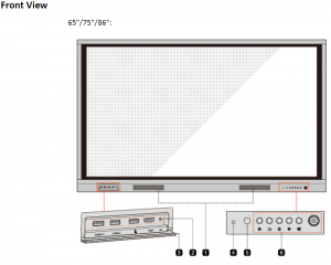

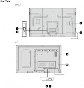
In addition to the above power and front connections below are the component connection ports:
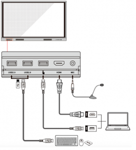
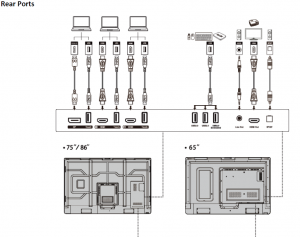
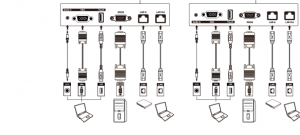
**For more information refer to the User manual that you have downloaded in the previous section
Final product
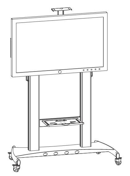
And the final result above. You now have a fully mobile touch screen solution ideal to move around. Please inform your customer of the following:
- The stand with LED weight cannot be pushed over rough terrain
- Cobble stone paths
- Rough laid brick paths
- etc.
- The stand is securely built but still has a lot of weight to carry around. Use the illustrated handles to push it around.
- It can be top heavy so if push with force at the top of the screen might result in unhooking or toppling over of the solution.
- The wheels are nice and smooth so a smaller LED such as the 65″ can be moved around easily by one person. When they have a 75″ or 86″ it is most definitely recommended that two people are utilized to move the solution
Installing the OPS PC:
Here are the steps to install the OPS pc if it is part of the solution:
Step 1 Unscrew the M3 screws by hand to remove the internal PC shielding cover.
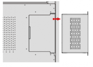
Step 2 Push the internal PC into the port at the rear of the screen from right to left.
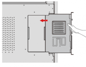
Step 3 Secure the internal PC to the display by using the M3 screws.
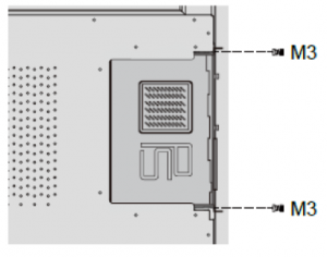
Step 4 Ensure the installation is correct before turning the power on again.
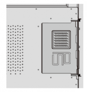
Once hooked on you can install additional add-ons as described in the Product knowledge section:
- Sound bars can be mounted on the bottom legs of the stand
- Using big cable ties to keep it in place
- Wireless presentation device can be placed on the accessory shelf
- Should you want to take the risk or are instructed to mount it at the back with double sided tape, make sure that you have an indemnity form signed and note this on your installation sign off form with customer signature next to it.
- VC (Video conferencing) system – Camera mounted on top of the LED on the VC stand that is installed and the Speaker pod either on the table or placed on the accessory shelf.
- An additional projector trolley could be purchased or further utilization of the accessory shelf for placing
- Visualizers
- Graphics Tablets
- Wireless casting device dongles
- Laptops / Macbooks Should an OPS pc not be present.
